PLC Logic for machine safety: what to modify and what to check

PLC logic for machine safety is one of the areas that may require attention when an existing machine tool has outdated or inadequate safety functions, or when these functions are no longer suitable for the machine’s current configuration.
However, improving machine safety is not simply a matter of modifying a few lines of PLC code. The process must begin with a risk assessment, followed by identifying the required safety functions, checking the devices already installed and determining how they should interact with the PLC, drives, sensors, interlocks and machine components.
On CNC machine tools, changes to PLC logic may be required, for example, to correctly manage automatic doors, permissive signals, stopping functions, protective devices or newly integrated automation systems.
For this reason, modifying PLC logic should be considered part of a broader machine safety and functional verification process, rather than an isolated software task.
When is it necessary to modify a machine’s PLC logic?
A machine may continue to operate correctly from a production standpoint while still presenting safety-related issues.
This is particularly common with machine tools that have been in operation for many years and have subsequently been modified or integrated with new devices and automation systems.
Changes to PLC logic may become necessary when, for example:
- guards or automatic doors are added or modified;
- new safety devices need to be managed;
- the machine is integrated with automation systems or peripheral equipment;
- access conditions to hazardous areas change;
- new movements or operating sequences are introduced;
- the existing logic does not correctly manage safety permissives;
- a previous machine modification has altered its original operating conditions.
Any modification should, however, be preceded by a technical assessment. Simply adding a permissive signal to the PLC or connecting a sensor is not enough to consider a machine safe.
PLC Logic and Safety PLCs: What Is the Difference?
The term Safety PLC refers to control systems specifically designed to implement machine functional safety functions.
A standard PLC can manage production sequences, movements, timing and interfaces with other systems. Safety functions, on the other hand, must be designed and implemented according to specific requirements based on the identified risks and the required performance level.
This distinction is important because a function that directly affects operator safety cannot be treated in the same way as a standard automation function.
Relevant technical standards include ISO 13849-1 and IEC 62061. ISO 13849-1 provides a methodology for the design and integration of safety-related parts of control systems, while IEC 62061 addresses the design, integration and validation of safety-related control systems for machinery.
In practical terms, the correct process therefore includes:
- hazard identification;
- definition of the required safety function;
- determination of the required safety level;
- design of the safety function;
- hardware and software implementation;
- verification and validation of the function’s behaviour.
Machine Safety: Why the PLC Is Not the Only Element to Check
Treating machine safety as an exclusively software-related issue is one of the most common mistakes.
A safety function may simultaneously involve:
- emergency stop devices;
- switches and sensors on machine guards;
- automatic doors;
- safety relays or Safety PLCs;
- contactors and isolation devices;
- CNC drives ;
- motors and spindles;
- solenoid valves;
- pneumatic or hydraulic circuits;
- CNC software;
- PLC logic;
- the operator interface.
Any modification to the PLC logic must therefore be consistent with the entire safety chain.
On a CNC machine, for example, managing an automatic door involves much more than simply controlling its opening and closing. It is also necessary to verify which conditions must be met before movement is permitted, what happens if the door is opened during the machining cycle, how the machine is stopped and which conditions must be restored before operation can resume.
It is precisely this integration of electronics, software, automation and machine tool expertise that makes machine safety upgrades particularly complex.
Machinery Safety Regulations: The Regulatory Framework
In Italy, machine safety must be assessed by considering both the legislation governing machinery as a product and the legislation concerning its use as work equipment.
Directive 2006/42/EC, implemented in Italy through Legislative Decree 17/2010, has historically represented the fundamental regulatory framework for essential machinery safety requirements. The legislation requires an approach based on hazard identification, risk assessment and subsequent risk reduction.
For machinery used in the workplace, Italian Legislative Decree 81/2008 is also relevant, as it regulates obligations concerning the use of work equipment.
Particular attention should be paid to machines already in operation. INAIL distinguishes between maintenance, improvement and modification of work equipment: a modification that changes the machine’s intended use or performance may have different implications from an intervention carried out solely to improve safety conditions.
The New Machinery Regulation
The European regulatory framework is also set to evolve with Regulation (EU) 2023/1230 on machinery, which will apply from 20 January 2027..
For companies managing a machine fleet, this makes it even more important to keep documentation, risk assessments, modifications and the actual configuration of equipment under control.
Each situation must nevertheless be assessed individually: machine compliance cannot be determined simply by the presence of a particular PLC or a certified component.
Machine Safety Inspection Checklist
Before modifying PLC logic, it is advisable to carry out a structured on-site technical inspection.
A preliminary checklist should include at least the following:
1. Machine Identification
- manufacturer and model;
- year of manufacture and installation;
- serial number;
- current configuration;
- any previous retrofit or modification work.
2. Documentation Review
- machine manuals;
- electrical diagrams;
- pneumatic and hydraulic diagrams, where applicable;
- CNC documentation;
- available PLC programs;
- documentation relating to previous modifications;
- available declarations and compliance documentation.
3. Safety Device Inspection
The presence and correct operation of the following should be checked:
- emergency stop devices;
- fixed and movable guards;
- interlocks;
- sensors;
- automatic doors;
- enabling and permissive devices;
- safety barriers or other protective systems.
4. PLC Logic Analysis
The technician must reconstruct the relationship between inputs, outputs, permissive signals, alarms and operating sequences, verifying that safety-related functions are consistent with the machine’s actual behaviour.
5. Stop and Restart Condition Verification
It is necessary to verify what happens when a safety device is activated and which conditions must be met before the machine can subsequently restart.
6. Integration Verification
If the machine has been connected to robots, loading systems, conveyors, automatic doors or other equipment, the assessment must also cover the interactions between the different systems.
Modifying PLC Logic Does Not Necessarily Mean Replacing the CNC
One of the most technically relevant aspects of working on existing machine tools is the possibility of carrying out targeted modifications.
A machine requiring a safety upgrade does not always need a complete CNC replacement or a full electronic retrofit.
Where the existing architecture allows it, modifications can be made to the PLC logic and associated devices, implementing the necessary changes and verifying the resulting machine behaviour.
In other cases, however, the assessment may identify the need for a more extensive upgrade, particularly when the electronics are obsolete, documentation is incomplete or the integration of new functions is not technically feasible within the original architecture.
The on-site technical inspection is therefore essential in determining the most appropriate solution.
How to Approach PLC Modifications for Machine Safety
For an HSE manager or control system designer, the starting point should not be “What PLC modification do we need to make?” but rather “Which safety function needs to be ensured, and how should the machine behave?”".
The necessary technical intervention can then be defined accordingly.
This is precisely the level of integration at which Assistec operates. Our electronic technical service includes modifications to machine PLC logic to improve safety in accordance with applicable regulations, as well as work on automatic doors, conveyor systems and other automation equipment. The service also includes on-site inspections to assess the safety of obsolete machine tools.
Machine tool expertise is a key factor: safety-related work must take into account not only PLC programming, but also the CNC, drives, electrical systems and the machine’s actual operating conditions.
Safety and Reliability Must Go Hand in Hand
Improving machine safety does not simply mean adding devices or modifying a program.
The objective is to achieve a machine in which protective systems, control logic, machine movements and operating behaviour work consistently together.
For this reason, particularly in the case of older CNC machines or equipment that has been modified over time, an on-site technical assessment is the most effective way to identify potential issues and determine the necessary corrective action.
Assistec provides specialised electronic and mechanical expertise for CNC machine tools, including technical assistance , retrofit services and system integration.
To assess the condition of an existing machine and determine which measures may be required to improve its safety, you can request an on-site technical inspection.
Recent Posts

-
PLC logic for machine safety is one of the areas that may require attention when an existing machine tool has outdated or inadequate safety functions, or when these functions are no longer suitable for the machine’s current configuration.
However, improving machine safety is not simply a matter of modifying a few lines of PLC code. The process must begin with a risk assessment, followed by identifying the required safety functions, checking the devices already installed and determining how they should interact with the PLC, drives, sensors, interlocks and machine components.
On CNC machine tools, changes to PLC logic may be required, for example, to correctly manage automatic doors, permissive signals, stopping functions, protective devices or newly integrated automation systems.
For this reason, modifying PLC logic should be considered part of a broader machine safety and functional verification process, rather than an isolated software task.
-
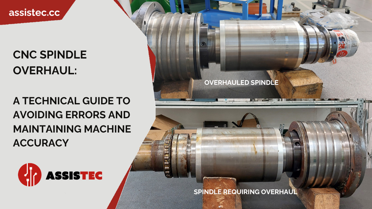
The CNC spindle is one of the most important elements of a machine tool: it is the component that transmits motion to the tool and, together with the machine’s other systems, determines precision, machining quality and production reliability.
When a spindle begins to show signs of wear, the problem is not limited to the component itself. Abnormal vibrations, loss of precision or increased noise levels can, in fact, compromise the entire production process, leading to scrap, premature tool wear and unscheduled machine downtime.
For this reason, the overhaul of CNC spindles should not be regarded as a simple repair job, but as a technical operation aimed at restoring the spindle to its original operating condition and ensuring stability and precision once again.
Relying on a professional service allows the real causes of the problem to be identified, worn components to be replaced and more serious faults that could halt production to be prevented.
-
Fanuc CNC Spare Parts: How to Identify Part Numbers, Check Availability and Reduce Machine Downtime
When a CNC machine tool comes to a standstill due to a fault, time becomes the most critical factor. Every hour of downtime can result in production delays, postponed deliveries and costs that often far exceed the value of the component to be replaced.
In such cases, finding the correct spare part is not simply a purchasing task, but a strategic step that directly affects the company’s operational continuity.
For this reason, understanding how Fanuc CNC spare parts work, knowing how to correctly identify spare part codes and being able to rely on rapid availability represents a tangible advantage for maintenance managers, procurement departments and mechanical workshops that work with CNC machine tools on a daily basis.